This page is found here:
"https://3ddoodle.com/intro-to-fusion-360/“
Get Fusion 360
Get the student/hobby version here:
https://www.autodesk.com/education/edu-software/overview?sorting=featured&filters=individual
Create an account and then download the application. It is cloud-based: you will need to be logged log in to use it. You can use it on only one computer at a time.
Learn about Fusion 360
You can learn about Fusion 360 from Lars Christensen on YouTube. There are slight differences in the user interface icons and a few names in the older version on the videos, but it doesn’t prevent learning design concepts and idioms. He has many dozens of videos on various topics, including using fusion 360 for general design, for CNC, for 3D printing, for sheet metal and more, that can all be done using the free version.
https://www.youtube.com/@cadcamstuff
Here is a good one to start with:
There are lots of videos out there from other folks too: you can learn about topics from any of them. There are hundreds of topics and some of them will be important for you, depending on what part(s) of Fusion 360 you use.
Finding Answers and Getting Help
Search for “fusion 360 how do I …” – there are a lot of answers out there. Half the battle is finding the keywords to search for, because there are vast numbers of users who have likely already made all the mistakes and misunderstandings.
The Autodesk support site:
https://www.autodesk.com/support
Ace Makerspace’s Cad-cam channel on its Slack instance:
https://join.slack.com/t/acemakerspace/shared_invite/zt-2avt1taye-uE3Ux68ytP9kOckS2iDkdQ
The Language of Shapes
One challenge with 3D modeling is that we ourselves do not have names for complex shapes. We only have names for simple, common shapes like a cube, sphere and torus, etc. A complex shape quickly outstrips our vocabulary. So, we resort to describing shapes because there is no alternative.
Fusion 360 is an amazing collection of tools for recording the description of a 2D and 3D things and then doing something useful with those descriptions. We can give it a name, but what it is within the system is what we have meticulously described it to be.
Once it has been described to the system, and also meets your needs, Fusion 360 can do useful things with it:
- produce files for a 3D printer or a slicer
- produce files for a laser cutter
- produce files for a metal CNC
- produce files for the wood CNC
- Produce drawings with measurements that can be shared with others
Most importantly, this 3D models you create in the system can be updated and the files can be re-exported. So there is a natural workflow:
- drawing something
- exporting it
- making it real
- testing it
- accepting the result or refining the drawing & starting over at “exporting it”
Projects, Documents and Components
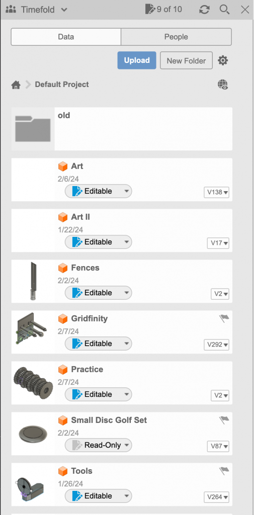
A student/hobby version of Fusion 360 allows you to have up to ten writable documents at the same time. You may have any number of readonly documents.
You may create any number of projects that can contain any number of documents and folders, which can also contain documents and folders. But, still across all projects and folders, only ten documents can be writable and the rest must be read-only. You can change their writability at any time.
Each document starts out with one top-level component. You can name it whatever you wish. Fusion 360 will add a version number to the name each time you save the document.
One style of use is to draw each part in its own document, but this is tedious with the student/hobby version. It is better to group models into a document by creating sub-components. This just means selecting the top level component and using the context menu to select “New Component”.
Any component can contain sub-components by selecting it a choosing “New Component” from the context menu.
Therefore, you can make groups of components or nested components, etc. You choose which component in the hierarchy is to be exported before you select “Export” from the file menu.
The Timeline
Drawing components is like creating a recipe for the component. While you can’t un-cook a cake, you can un-cook a drawing. You can step backwards in time and see individual changes you made to your 3D model disappear one-by-one. It is like going backwards in a book you are reading. The rest of the book still exists past where you are now looking, and you remember it. So does Fusion 360. But, you can make changes anywhere in the timeline. You could add something, or change or delete it. If you step on the wrong butterfly in this process, you can use the Undo function, or you could go back to the last version you saved. It is easy to “break” a 3D model and unless you understand what caused it to break, it can be difficult to know how to fix it.

Control of the timeline is incredibly useful. Usually when you are editing you want to be sure you are at the end of the timeline (all the way to the right). But, sometimes you want to go back in time, change something simple like a dimension or which parts of a sketch are selected, and then go back to the end of the timeline and see the result. Sometimes this works and it is almost magical.
The rest of the time the timeline ends up with one or more of the icons that have yellow or red backgrounds. You changed something that was depended upon by something later on, and the change you made confused Fusion 360 and it needs your help to fix it.
You also use the timeline as a menu so you can interrogate each step in the drawing, regardless of its color. You can open a single step up and change its parameters. You can suppress it so it seems like it was not there at all but is easy to put back. You can rearrange the steps. Sometimes you can fix what you broke. Sometimes it is just easier to redraw it.
You navigate back and forth and to any part of the timeline either by dragging the timeline cursor or by using the playback controls to the left of it. What you see in the workspace after moving the timeline cursor is what your 3D model describes if you stopped at that point. If there is yellow or red to the left of the timeline cursor, the system might not even be able to draw anything at all. You can export or copy it from any point in the timeline.
The Undo/Redo Stack
The undo/redo stack in Fusion 360 is like that in many other applications. There are buttons above the command bar to access undo and possibly redo.

If you keep clicking “Undo” the document goes back to its initial condition, which is an empty component awaiting your first drawing command.
The stack records each thing you do to any component in a document, including any interaction with the timeline, switching to edit other components, hiding and revealing objects, copy/paste, remove and delete. But not exporting a file. The stack and the timeline are independent of each other and the stack sees all.
Let’s assume you have drawn a complex object. Then, the next day you sit down to make some improvements and they don’t work the way you expect. That actually happens a lot. So, if you happen to like what you see, or if you would consider it a “save point” in a game, then save the document. But, before you restore an older version, you might consider clicking Undo and letting Fusion 360 catch up, and then repeating those two things (undo and wait), until you get back to the point right before you began to make improvements.
More often, you’ll be working on a drawing and the wrong thing happens from what you expected or because of an errant click or drag or keyboard interaction. Then it all went wonky. It is easier to just say “OK” and let Fusion 360 spin its wheels on a new rendering of it, and then you just click “Undo”. Those two steps are easy to remember and always work. Fixing it by editing more is like “going forward to go backward”. Editing out mistakes can be harder and may even be inferior or even problematic problematic compared with using undo.
Like undo there is also redo. It lets you go forward through the stack. Once you begin adding new edits to it, the redo function goes away until the next time you use undo.
You Are Here
The largest part of the Fusion 360 workspace is for drawing things in 3 dimensions. It is a space with an up and down and left and right, like the one we live in. You can draw things at any angle or on any plane. It doesn’t matter. After you export a file, it can be oriented however you need by the tools that use that file.
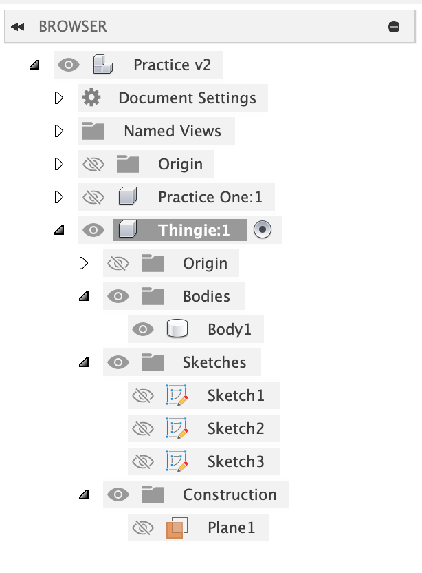
Each 3D model you create will live inside some component inside of some document. There can be many components in a document. The document is organized the same way a directory structure is organized: a hierarchy. At the very top is the top level component with its various groupings of things and any sub-components with theirs. The hierarchy is up to you and can be as deep as you wish.
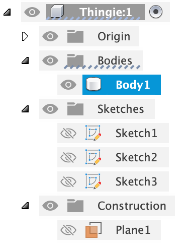
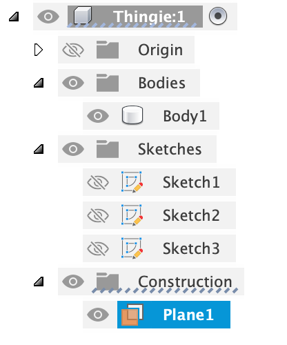
Inside any component, aside from any sub-components, you’ll find groups of objects related to that component and available to sub-components:
- Origin
- Bodies
- Sketches
- Construction
The more you draw, the more objects will accumulate here. You can make them invisible so your work area doesn’t become confusing or difficult to use.
Selecting a Component to Edit
Before you edit a component, you must tell Fusion 360 which component you are editing within the document being displayed. You can open many documents at once, but only one is displayed at a given time and the others appear as tabs above the command icons.

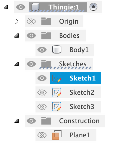
To select a component for editing you must click its radio button to the right of its name. Whichever component has its radio button clicked is the one receiving the edits or additions you are making. It is remarkably easy to mess up a different component because you forgot to click the one you intended to edit.
Do not be confused by the visibility of the component, which is controlled by the on/off eye to the left of a component’s name. It has no effect on the target of what you are editing. It is easy to be looking at one component and editing another and feeling confused why it doesn’t work the way you expect.
You can only ever edit one component at a time.
When you add a new component you must select its parent component, which could be the top level component or a subcomponent, etc.
The Origin
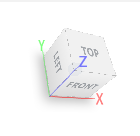
You are drawing in a 3D space. Once you’ve drawn something you’ll feel oriented simply by looking at what you’ve drawn. But, until then, look in the upper right corner to see a small cube with words like “Front”, “Top”, and “Bottom” , etc. You can click and drag that around, or click on the names, or you can click on the little home icon just to the upper left of the cube.
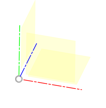
The origin contains a set of objects that are often useful when drawing. These are the three intersecting planes of this 3D space, plus the three axes formed where these planes meet. Plus, the point where all three planes meet. It is the middle of the empty document. You need planes and you often need a center point, and these already exist – they come free in every new component.
It is common to hide the origin when you don’t need it and bring it back whenever it is needed, but you can also leave it there.
Bodies
Bodies are the things you draw or create. They don’t have to have volume per-se, but they are some set of edits – a recipe for a thing. They might use the origin. They were created on a timeline and when you copy a body, you copy the timeline that created it. A body cannot be exported the way a component can be exported. But, you can convert bodies into components.
You can hide bodies while you are editing others. Hiding affects which objects are exported. The undo stack remembers hide/show maneuvers too.
You can also remove a body, which adds a step to the timeline to make the body disappear from that point onward.
You can rename bodies to something meaningful – this makes it easier to use them for some commands.
Sometimes you have to hide a body to be able to work on a body that is behind or very close to it.
Sketches
A sketch is (usually) a 2D drawing that is on some plane or another. It could be one of the planes in the origin. It could be a plane corresponding to a flat spot on an object you are drawing. You can also make a plane some distance from any other plane or flat spot. Once you have a suitable plane, you create a sketch on that plane.
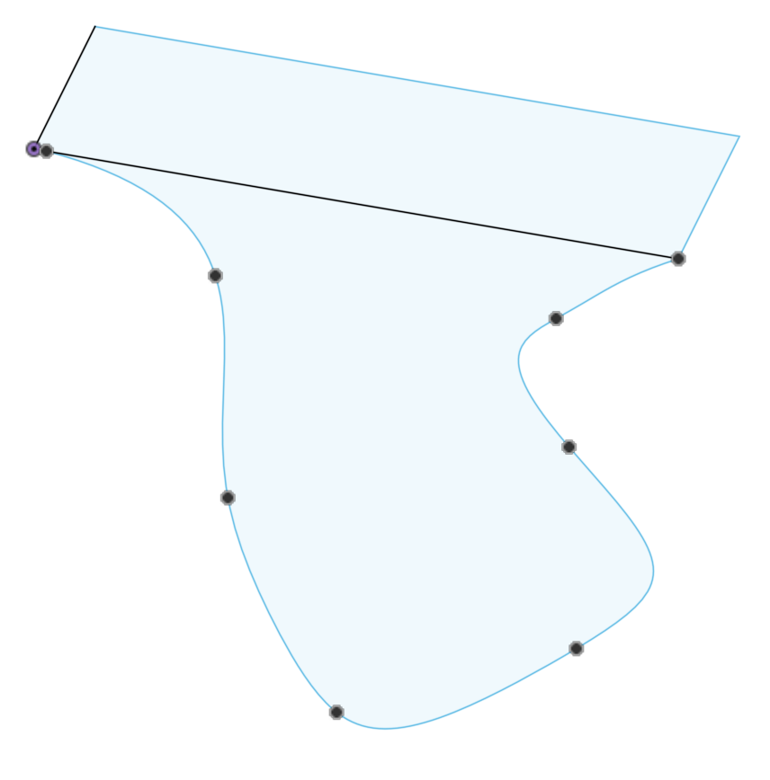
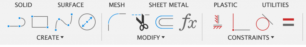
A sketch is where you draw things like lines, splines, circles, rectangles, hexagons and lots of other primitive shapes. You build up more complex shapes by using combinations and throwing away the parts that aren’t important to your drawing.
You can specify lengths either with numbers or you can create parameters to contain those values. Then you use the parameter names in your drawings so that changing a parameter later avoids the need to edit the drawing itself before producing new output files.
When you finish a sketch, an object shows up in the group of sketches. You can give a sketch a name and it can be hidden or visible, like bodies. If it is visible, you can use its various parts in other commands available when not editing sketches.
One of the cool things you can do with a sketch is change which plane it is on.
If a part of a sketch describes a closed object (no gaps in the perimeter) then that part of the sketch turns blue. Only a blue sketch can be used with many commands, such as extrude and loft.
It is normal to hide sketches when you don’t need them anymore.
Construction Lines in Sketches
While editing a sketch you can select any line (or circle, or spline, etc.) and then type X on your keyboard to toggle between a normal line and a construction line. A construction line appears as a dashed line, not a solid line. By default regular lines are created by the various drawing tools.
Construction lines are useful for aligning things, but they cannot be selected as part of a profile. For example, the loft and extrude and revolve tools cannot use a profile defined by construction lines. These tools are blind to construction lines.
Construction Objects
Many of the idioms you will use when drawing amount to figuring out how to create a plane where you need it so you can build a sketch there and then using one of the solid modeling primitives to create your 3D model based on the sketches you made.
Other idioms require you to create a line, not a plane. In Fusion 360 a line is called an axis.
You can construct planes and lines and also points. When you create these, they appear in this group and you can rename them, hide them and show them like the other objects above.
It is normal to hide construction objects when you don’t need them anymore.
The Tools Are On Top
There are a lot of tools. There are so many tools, that there are categories of categories of tools in fusion 360, and most of them have lots of options you can tweak. A menu simply would not be very practical.
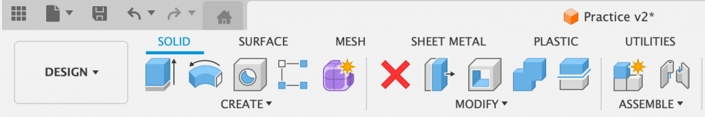
Fusion 360 first arranges broad categories of tools, such as “Solid”, “Surface”, “Mesh” and “Sheet Metal”. If you click on the name of a category the icons along the top change too. Each of these broad categories are like a workspace that are all working on the same 3D model. When you build an object in one workspace it appears in the list of objects you can show, hide and rename.
There are idioms that involve objects created in one workspace that get used in another. Start practicing in the solid workspace. The workspaces are designed to leverage what you know from other workspaces.
Every workspace has a Create and a Modify menu under the icons. The icons are a small selection of common tools. The menus contain all the tools.
Usually you have to create something before you can modify it. Many idioms involve creating a thing and then modifying it in interesting ways. But, also, modifying is just another brush stroke, a step in a series of changes to make something just right.
Some tools should be used later than others. In particular, operations like fillet and chamfer should be done as late as practically possible in the design. They tend to complicate a drawing, making it harder to modify. Sometimes the best bet is to either use the timeline to go before the chamfer or fillet, or delete them and create them again after the editing is done.
When you create a sketch you automatically enter the Sketch workspace and when you finish a sketch you automatically leave the Sketch workspace and return to the one you were previously in, probably the solid workspace. The icons have a different style in each workspace, but there are lots of analogs across workspaces. There is an extrude function in both the solid and surface workspaces, for example.
Navigation
If you use a 3D input device it will have its own navigation idioms that you can customize.
You can also use the navigation icons at the bottom of the workspace.
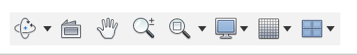
Click the leftmost button and the click and drag on the workspace to rotate the view of the object about the origin, the same effect you get with the navigation cube in the upper right corner of the workspace.
Click the second icon and then click any plane. Fusion 360 will rotate the view so you are looking directly at that plane straight on. You can click on construction planes or flat parts of your 3D model.
Click the hand to move the view of the object left or right or up or down.
Click the magnifying glass icons to zoom in or out.
If you use a regular mouse you can drag a drawing around with a middle mouse button. Fusion 360 is harder to use with a 2-button or laptop mouse, but not impossible. You can zoom in and out by rolling a thumb wheel.
There is a difference between changing your view of an object and moving an object to a different location within the workspace. There is a use for both, but mostly for the former. Mostly you will want to change your view. If you accidentally move a body instead of your view of it, you will be asked if you want to capture the current position or revert to their original position whenever you are finished the current edit or addition.
Constraints
When you are creating a sketch one of the ways you can influence the 3D model is by creating constraints that limit where parts of the sketch can be, how they are aligned or how they are connected. Constraints allow you to describe parts of a model using named relationships, such as “parallel” or “perpendicular” or “colinear” or “coincident”, which means that two things are in the same place, such as the center of two circles.
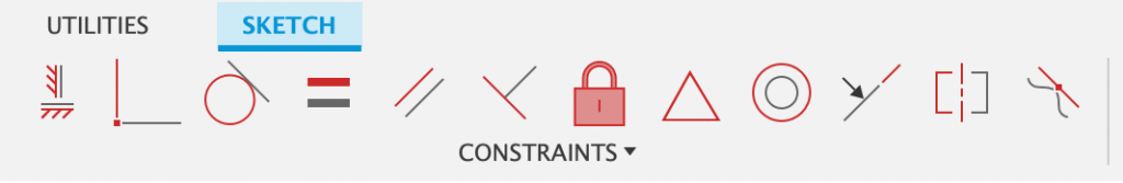
Constraints are better than numbers if you have the choice of using either. Constraints adjust automatically. For example, if you indicate that a line is tangent to a circle, and then drag the other end of the line around, the first end remains tangent to the circle.
With enough constraints nothing can move and a sketch changes from blue lines to black lines. It is possible for some parts of a sketch to be black and some blue. A blue sketch can still be used by other commands, but if you make changes earlier in the timeline a blue sketch will be more likely to fail and need to be edited again.
If you make a change earlier in a timeline and break a constraint, you can reassign it to fix it, or you can delete the constraint.
You can delete a constraint, but some objects like rectangles create a lot of constraints in a single action, and deleting them can be tedious, so you can delete the object and the constraints go away with it.
Common Idioms – Things to Learn
Here are some common idioms that can be useful for drawing and working with components:
- Draw using constraints as much as practical
- Use dimensions to make it possible to make changes easily by clicking them later
- Define parameters for all the important measurements in your sketches and use their names instead of numbers
- Use parameters in all of the various create and modify tools when they ask for input values for things like lengths and counts
- Create cylindrical holes in a model and use the thread function to create threads there
- Use the center point of the origin to help align components
- Use the origin planes to help align components
- Draw a sketch and extrude (press/pull) a shape to create or join a body
- Draw a sketch and extrude (press/pull) a shape to remove from a body
- Construct a plane and then use it to split a body into two or more bodies
- Combine two or more bodies into one body
- Repeat a pattern in a circle some number of times
- Repeat a pattern in one or two linear directions
- Draw two profiles with sketches and connect them with a loft
- Create a coil and use it to create a helical path for a sweep
- Project a shape from one sketch into a different sketch on a different plane
- Copy a body from one component to another within the same document
- Create a sketch and revolve it around an axis
- Create a surface by extruding a solid, then use that surface to cut other solids or other parts of that solid
- Create a form, modify it and convert it to a solid body
- Create a mirror in a sketch across some line so you only need to draw one side of a shape and the other is automatically drawn and updated
- Create a mirror of a 3D body along some plane so you only need to create one half of it and the other is automatically drawn and updated
- Move bodies around, especially if you have just pasted one, or have drawn separate bodies that aren’t oriented correctly for your needs.
- Copy a component and then select a new parent in the same document and use “Paste New” to produce a duplicate component with its own timeline.
- Use Derive to bring a component from one document into another, and use “Break Link” to effectively make a copy within the document instead of using it by reference from the other document (which happens by default).
About Exported Files
You can export your model in a few different formats via the Export selection in the file menu. The file menu is very close to the undo and redo buttons at the top of the window, above the tool icons. It is second from the left in this image.

- .stl files. STL stands for Stereo Lithography and the file defines triangles without any information about the size of the model. It has no design information in it. Fusion 360 can import a .stl file and it becomes a mesh. You can convert a mesh to a body that can be edited. Also, meshes themselves can be edited.
- .step files. STEP stands for Standard for the Exchange of Product Data and is also known as ISO 10303. It contains enough information to know the size and scale and to potentially edit the file. Fusion 360 can import a STEP file and you can convert it to a body that can be edited, but it has no timeline – you cannot edit its sketches or other drawing steps.
- .f3d files. This is the native Fusion 360 file format. These files serve as a backup for whichever components are selected. Select the top level component to create a copy that could be loaded into someone else’s Fusion 360 account, or be archived for release management. These files contain the entire timeline for the included components.
- There are lots of other formats for different purposes and for exchanging models with different kinds of systems.
3D Input Devices
A 3D input device can make Fusion 360 easier and more efficient to use. There are controllers that work like a 3D mouse, or a drawing tablet you use with a special pen, etc.
I use a USB SpaceMouse from 3DConnexion:
https://3dconnexion.com/uk/spacemouse/