Assembling the Spool Rotator
Preparation
- Order components and print the essential parts:
- See the download page for a list of the essential and optional parts.
- Six 608zz bearings:
- Two 8x120mm threaded rods (or longer):
- 8mm hardware kit:
- https://www.amazon.com/dp/B0B4FPBP8D
- I also used some of these lock nuts: https://www.amazon.com/dp/B0BBQJXNBG
- 47 6x2mm strong neodymium magnets:
- Prepare a shelf over your printer
- About 40-50cm above the top of the extruder at the top of its travel
- Ideally you can change the height of the shelf if you need to
- You’re going to drill holes in the shelf, is that OK?
Assembling the Spool Rotator
- Insert bearings into the two spool flanges. Insert the two flanges into opposite sides of a spool with a 55mm center hole. The flange with the pulley must not slip.
- If the flange doesn’t fit snugly you’ll need to use one of the Spool Flange Sleeves on both sides of the spool. They prevent the spool from sliding on the spool pulley flange and ensure smooth operation.
- Insert three bearings into the top block.
- Insert an 8mm bolt through the middle bearing. It must be long enough to go through the support shelf and the top magnetic pinion gear and the top nut holder plus another 12mm. Enough of it must protrude through the top nut holder to receive a pair of nuts.
- Use the top magnetic pinion gear as a template to mark the shelf where the spool rotator will hang. It is best of the shelf height can be adjusted so you can raise or lower it as needed. Mark four positions for a 5mm hole and the center for a 9mm hole. These are slightly larger than the hardware for ease of assembly.
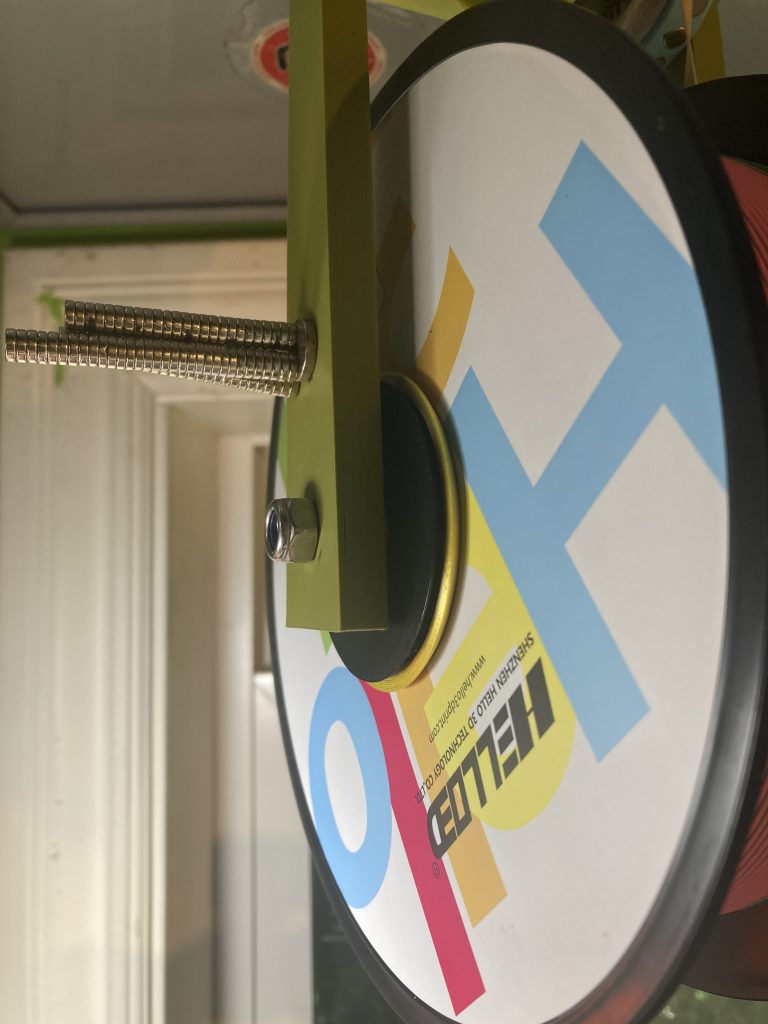
- Glue magnets all in the same polarity direction into the top magnetic pinion gear.
- Glue magnets all in the other polarity direction into the magnetic pulley gear so that the two gears attract each other.
- NOTE: You can instead print the optional magnetic pulley base so you can use interchangeable top pulleys instead of the fixed size top pulley.
- Insert a bearing into the pulley gear.
- NOTE: You can use any of the various pulley gears.
- Insert an 8mm threaded rod through the two aligned bearings in the top block.
- Place the magnetic pulley gear on the short side of the top block.
- Place an arm over each end of the threaded rod in the top block and hold them in place with a nut on each end.
- NOTE: Locking nuts (with a nylon insert) can help avoid the nuts coming off.
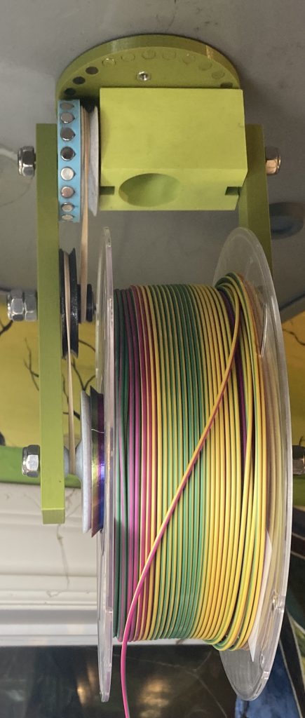
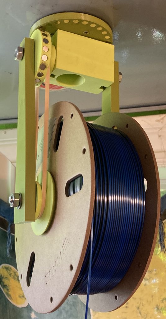
- Insert a threaded rod through the open end of one arm, through the two spool flanges, and finally through the other arm. The spool pulley flange must be on the same side as the magnetic pulley gear, so that a rubber band can go between next.
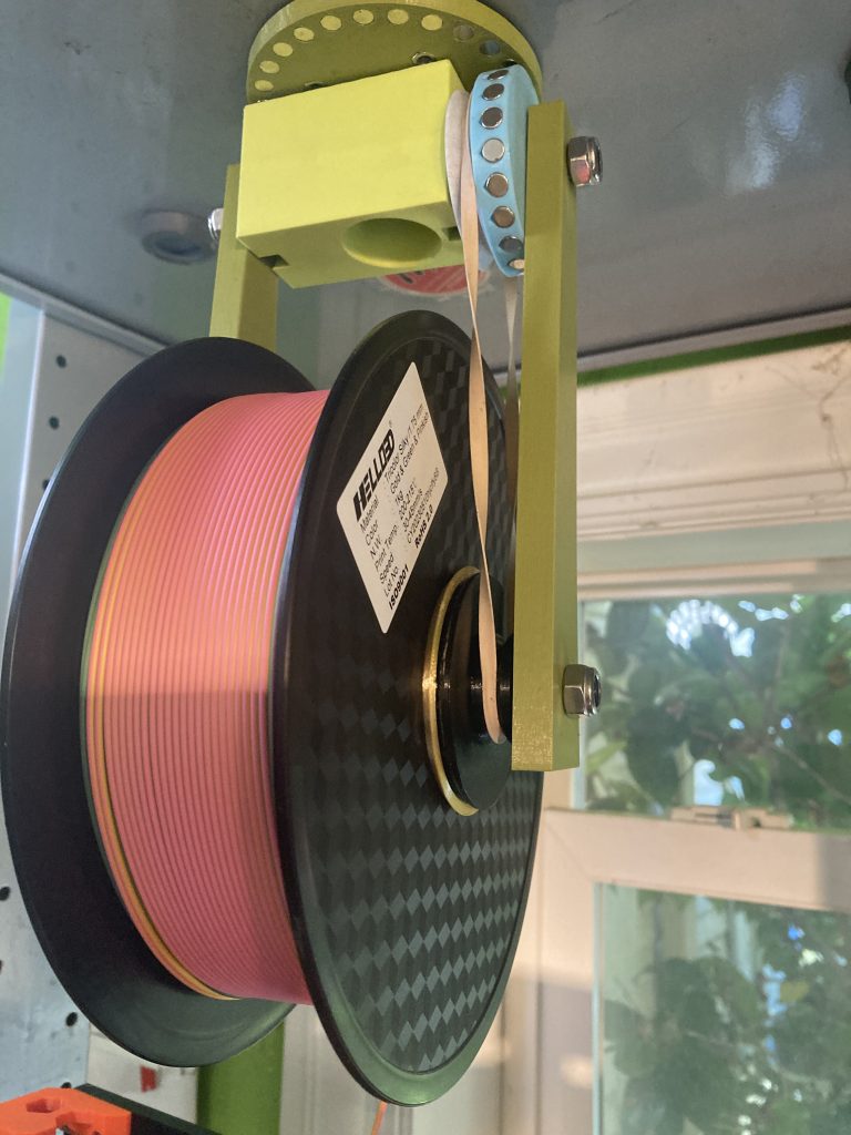
- Temporarily pull the arm off the threaded rod by the pulley flange and add the rubber band between the two pulleys. Put the arm back and secure both arms with a nut on each end.
- Insert 4mm nuts into the top magnetic pinion gear.
- Drill the 5mm and 9mm holes you marked through your shelf.
- Use 4mm bolts through the shelf to hold the top magnetic pinion gear in place, engaging with the nuts on the underside. Do not allow the bolts to go through the nuts far enough to interfere with the block’s rotation! Use nuts or washers on top if the bolts are too long.
- Put a bearing into the top nut holder.
- Insert the bolt in the block through the top magnetic pinion gear’s central hole, through the shelf, through the top block and secure with a nut. Tighten the nut enough to get the two magnetic gears to touch but ideally the block doesn’t drag against anything.
- Add a second nut on top to lock the first nut in position. Use the double nut method and not a locking nut because you need to adjust the position of the nuts to get the magnetic gears as close as possible or touching.
Note: The spool is off-center by design so that the center of gravity pushes the magnetic gears together.
To mount a spool see the instructions for changing spools here:
Optional
Here are some optional things you might want to print:
- Tube-Type Filament Guide
- Interchangeable Top Pulleys and Magnetic Gear Base that accepts pulleys
- Interchangeable Bottom Pulleys and Spool Pulley Flange Base that accepts pulleys
- Spool hub hole adaptors (aka Flange Sleeves) so spools with different sized hub holes can be used.
- Hanger Arm with Idler Pulley
Tube-type Filament Guide
I have tried ring-type filament guides but they are too thin. The Tube-type filament guide works much better. There is a lot more information about it on the download page. You should definitely download it and install it if you plan to print anything bigger than about 50mm in diameter.
Position it directly under the center of the spool, a couple inches below the spool.
All about the tube-type filament guide
Interchangeable Top Pulleys
You can print the Magnetic Pulley Base and one or more of the interchangeable small pulleys (up to 50mm) and use those instead of the original Magnetic Pulley Gear. If you print these you will be able to change the speed of rotation by changing the top pulley size.
Interchangeable Bottom Pulleys
You can print the “Spool Pulley Flange-Base” and any of the interchangeable pulleys and use those instead of the original Spool Pulley Flange. If you do you will be able to change the speed of rotation by changing the bottom pulley size.
There is also a “Spool Pulley Flange – Small” and another called “Smallest” which is the smallest practical pulley size. It wasn’t possible to use a separate pulley for these smaller sizes. You could print either of these instead of or in addition to the other pulleys and the Spool Pulley Flange-Base.
Also, the Spool Pulley Flange-Base actually works as a SpoolFlange so you could just print the Spool Pulley Flange-Base twice and use it for both sides of the spool. It works, but doesn’t look intentional. It looks like it was poorly designed, because 2mm of the bearing stands out.
Spool Hub Hole Adaptors (Sleeves)
There is no standard for the size of the hole in the hub of a spool. There is a set of sleeves that fit over the original 55mm spool pulley flange and spool flange. These fit snugly and effectively increase the diameter by 2 or more mm in 1mm increments up to an additional 15mm in diameter. That extends the range from 55 up to 70mm. You use them in pairs.
For more information, photos and a sizing chart, see the Flange Sleeves section of the download page.
Hanger Arm with Mid Pulley
Even the smallest bottom pulley and the largest top pulley yield colors that change too fast for large prints that use a lot of filament. To slow the color change even further you can use the optional “Hanger Arm For Mid Pulley” and the “Mid Pulley Reducer“. You’ll need an M8 x 30mm bolt and a locking nut and some washers too.
The bolt only fits into the mid pulley from one direction. The bolt goes through the middle hole in the support arm and a combination of washers and a locking nut go on the outside.
Then you put a smaller rubber band between the large mid pulley and the small pulley on the Spool Pulley Flange. Put another rubber band between the small mid pulley and the Pulley Gear (with the magnets). It looks like this: